In this assignment, you are required to create a basic graphics program using OpenGL. As you have learned during class and tutorial, to start up your graphics program, you will need to use GLFW to create a window. By default, GLFW will create a window with double buffering enabled. Then, you can use the basic OpenGL calls to draw 3D objects on the window as well as manipulate the camera to navigate through the virtual scene. To reduce aliasing artifacts, you can also enable anti-aliasing in OpenGL by multi-sampling.
In the following, we will give you the specifics about what you need to accomplish, as well as some related guidelines to assist your programming.
Before doing the assignment, it is recommended to read the materials on OpenGL programming at OpenGL Tutorial, OpenGL tutorials and notes. You can also read Learn OpenGL which conducts OpenGL rendering based on OpenGL Mathematics (GLM) library.
In addition to programming, you will also need to demonstrate your code to TAs.
Things you should prepare:
Additional Notification:
You are required to submit the following things through the GitHub repository:
Report/ folder.
Submissions without the Report PDF will not be
scored.
Submission deadline: 22:00, October 15, 2025
The skeleton program and report template will be provided once you accept the assignment link of GitHub classroom which will be given below. If you accept the assignment through the link properly, a repository that contains the skeleton project and the report template will be created under your GitHub account. Please follow the template to prepare your report.
You should complete your assignment submission to your repository through GitHub before the deadline.
Accept the assignment through this link or download the zip file to start your assignment.
You will need CMake to build your code. To build the project, firstly you need to download CMake if you do not have one. Then run command
mkdir build
cd build
cmake ..
cmake --build .
These commands first make a directory whose name is "build" After that, it uses CMake to configure the project and builds the project.
Besides, we recommend using Visual Studio on Windows and Visual Studio Code on Linux. Both of them can build the CMake-based projects automatically (maybe with help of some plugins). If you are already an experienced developer, you can choose whatever you like. (You are encouraged to use clang+clangd+llvm+ninja on linux or windows. To generate the compile_commands.json file, which can help you manage your code through vscode, you can use the following command: cmake -Bbuild build/ -DCMAKE_EXPORT_COMPILE_COMMANDS=True -G Ninja, then you can use the following command to build your project: cmake --build build/ -j)
We have already created a blank window for you to start your drawing. You should expect the following result.
We define a simple mesh file that can represent 3D mesh objects with vertices, normals, and triangle face indices. We provide three object files in assets directory, ("bunny", "plane" and "sphere) that require you to load by yourself with the following format:
int int int

float float float
...
float float float

float float float
...
float float float

int int int int int int
To be more specific, the first line contains 3 integers, namely the vertex count, normal count, and face count. Then there follows as many lines as the vertex count, where each line contains 3 floats representing the position of a vertex. For the next lines with the line count equal to the normal count, where each line contains 3 floats representing the normal of a vertex. And according to the face count, there are extra corresponding lines. Each line contains 6 integers v0, n0, v1, n1, v2, n2, where v0, n0 means the vertex index and normal index of the first vertex, v1, n1 means the vertex index and normal index of the second vertex and v2, n2 means the vertex index and normal index of the third vertex.
Here, we give an example of a plane mesh file as below.
4 1 2

-1.0 1.0 -1.0
1.0 1.0 -1.0
1.0 -1.0 -1.0
-1.0 -1.0 -1.0

0.0 0.0 1.0

0 0 1 0 3 0
1 0 2 0 3 0
You need to implement the function
loadDataFromFile() in "mesh.cpp" to load all
the data of the mesh from this simplified mesh file. You can
organize the data with the provided vertex structure in
"mesh.h" and save the vertices into the
Mesh object for rendering:
struct Vertex {
  vec3 position;
  vec3 normal;
};
You will find that a drawn mesh does not appear to be 3D if it is filled with one color. The reason is that you do not have a lighting model applied to give the appropriate shading on its appearance.
Phong lighting model is an approximation of the lighting in the real world, which is easy and efficient to implement.
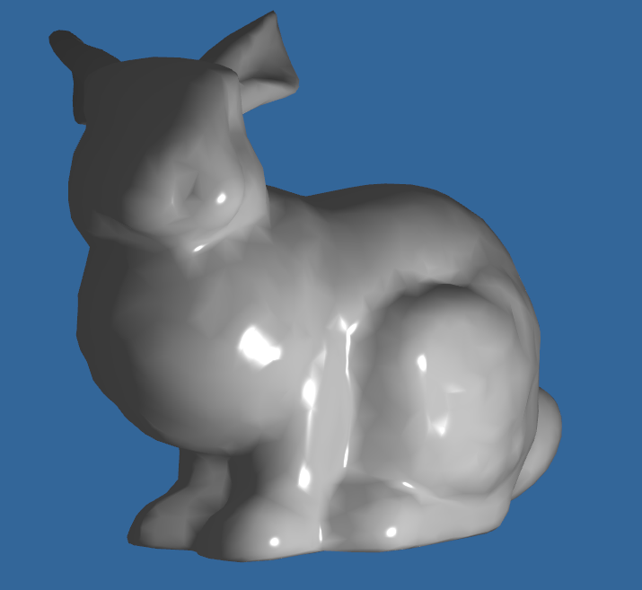
The OpenGL lighting model considers the lighting to be divided into three independent components: ambient, diffuse, and specular. All these components are computed independently and then added up together. For a more comprehensive description, please follow the link above. After implementing this light model, the rendering effect will be much more exciting!
Here we provide an example rendering result of the bunny object.
To navigate in your virtual scene, you need to change your camera from time to time.
We only have to specify a camera position, a target position, and a
vector that represents the up vector in the world space (the up
vector we used for calculating the camera/view coordinate system),
and the OpenGL will help you construct the view matrix by
gluLookAt(...).
If we want to achieve the pitch and yaw of the camera, we only need
to change the target position that the camera looks at in
gluLookAt(...). If we want to roll the camera, we will
need to change the up vector in gluLookAt(...). To move
the camera, we change the camera position in
gluLookAt(...).
As described above, we can define the camera view matrix through
gluLookAt(...). By changing the camera position in this
matrix, camera translation can be achieved.
As you have learned in class, the camera coordinate system can be described by 3 vectors: up vector, forward vector, and the right vector. To move the camera forward and backward, you should calculate the movement increment along the forward vector (positive or negative) based on your keyboard input, and then update the camera position using this increment. To move the camera left and right, you should calculate the movement along the right vector based on your keyboard input and update the camera position using this delta movement vector.
To respond to the keyboard input, you should implement a function to process the input like below:
void processInput(GLFWwindow *window)
{
  ...
  float cameraSpeed = 0.05f; /* adjust accordingly */
  if (glfwGetKey(window, GLFW_KEY_W) == GLFW_PRESS)
      cameraPos += cameraSpeed * cameraFront;
  ...
}
And you may need to call this function to update the coordinate inside the render loop.
To be able to change the viewing angle, we need to change the camera's forward vector based on the mouse input. The yaw and pitch values are obtained from mouse (or controller/joystick) movement where horizontal mouse movement affects the yaw and vertical mouse movement affects the pitch. To capture and process mouse input, first, we have to tell GLFW that it should hide the cursor and capture it:
glfwSetInputMode(window, GLFW_CURSOR, GLFW_CURSOR_DISABLED);
Then, we should define mouse input callbacks:
void mouse_callback(GLFWwindow* window, double xpos, double ypos)
{
  ...
  // Here is how you process mouse inputs
  ...
};
Then, you should register it to OpenGL:
glfwSetCursorPosCallback(window, mouse_callback);
When handling mouse input for a camera, there are several steps we have to take before eventually retrieving the direction vector:
Check more from this site for OpenGL camera transformation.
Looking forward to your exciting work!
Copyright 2025 ShanghaiTech University